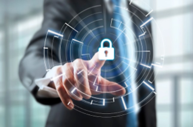
Advanced Security and Surveillance Solutions for a Safer, Smarter Organisation
Interactif Video Systems (IVS) delivers comprehensive security and surveillance solutions designed to safeguard organisations across all sectors. From consultancy and system design to testing, commissioning, and ongoing support, IVS provides a complete suite of services for every type of security surveillance system.
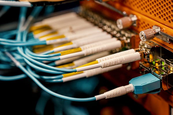
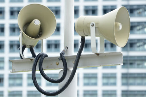
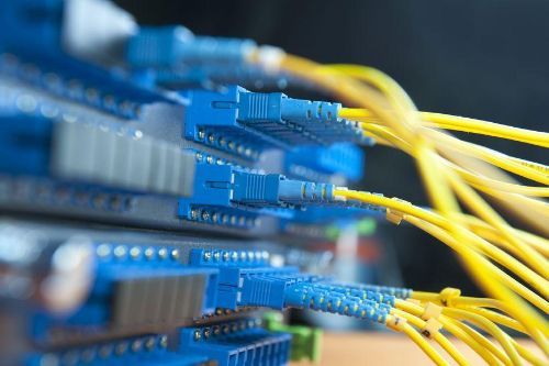
You can also enhance your overall security setup with our integratedPublic Address System for clear on-site communication and our advancedNetwork Solutions to ensure your surveillance infrastructure operates smoothly and reliably across all locations.
Backed by strong partnerships with leading global brands and a commitment to independence, IVS delivers customised, cost-effective solutions built on decades of expertise, helping businesses stay ahead with the latest in surveillance innovation.
Why Choose Our Security and Surveillance Solutions?
End-to-End Expertise
IVS provides consultancy, design, installation, testing, commissioning, and ongoing support for every type of security surveillance system.
Advanced Technologies
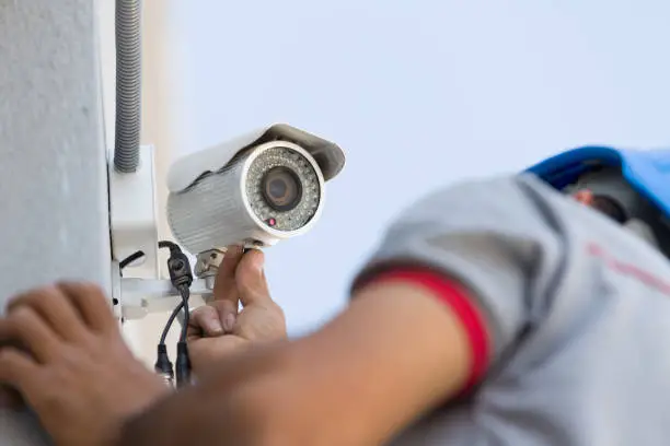
From high-performance security surveillance camera system setups to integrated monitoring platforms, we deliver solutions built for reliability and scalability.
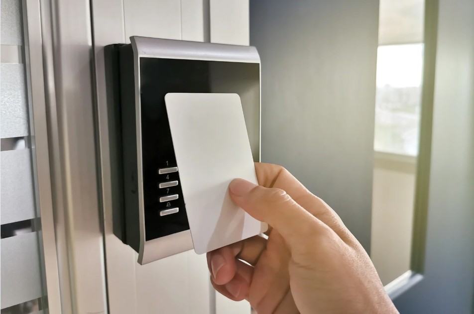
Customised Access Control
We design and implement tailored card access system solutions, including secure and compliant options for card access systems in Singapore.
Future-Ready Protection
With continuous support and expert guidance, we help organisations stay updated with new and emerging surveillance innovations.
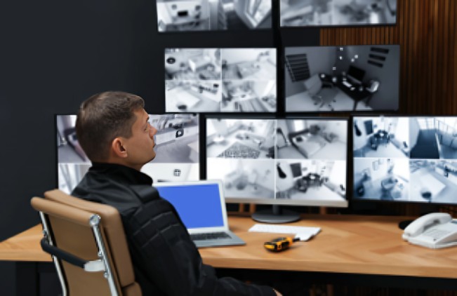
Security Solutions for Enterprises and SMEs
At Interactif Video Systems, we provide tailored security surveillance system solutions for two key market segments—large enterprises and small to medium-sized businesses (SMEs). Because each has different monitoring, scalability, and installation needs, we ensure every client receives the right level of protection and functionality.
Our enterprise solutions are built for large-scale operations, multi-site facilities, and complex security environments. These setups often require advanced integration, extensive monitoring networks, and sophisticated security surveillance camera system deployments. We support enterprises with centralised monitoring, multi-layer access control, and customised system architecture to meet stringent operational and compliance requirements.
For SMEs, we focus on flexible, cost-effective systems that are easy to deploy and maintain. Our solutions deliver essential coverage, simplified monitoring, and scalable configurations that grow with your business. We combine CCTV, streamlined access control, and cloud-ready monitoring tools to keep security strong without adding unnecessary complexity.
Whether you’re managing a large enterprise or a growing SME, we design surveillance solutions that align with your scale, security priorities, and budget—ensuring reliable performance across all applications.
A security surveillance system helps monitor and protect your premises using cameras, sensors, and integrated control tools. It enhances safety, prevents unauthorised access, and supports incident investigation.
We offer a range of security surveillance camera system options, including IP cameras, thermal cameras, and analytics-enabled solutions tailored to your operational needs.
Our team evaluates your space, risks, and budget to recommend the most suitable security surveillance system. If you’d like expert guidance, feel free tocontact us.