network

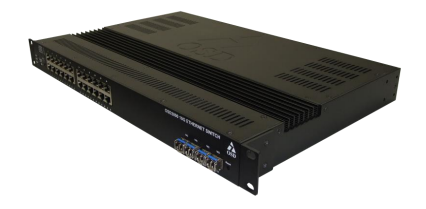
OSD2890 L2 MANAGED 24 x 10/100/1000BASE-T & 4 x 10G SFP+ ETHERNET SWITCH
PRODUCT DESCRIPTION
- Complies with IEEE802.3I/802.3u/802.1ab
- 10/100/1000Base-T, IEEE802.3z 1000Base-LX,
- IEEE802.3ae 10GBaseXX standards
- Supports RSTP/STP/ ITU-TG.8032 Ethernet Ring
- Protection Switching for Ethernet redundancy
- Supports Loop Protection
- IP Multicast Filtering through IGMP Snooping V2
- Supports port-based VLAN and Private VLAN
- QoS with eight priority levels
- Virtual USB console, Telnet, SNMP V1, V2c & V3 and Web Browser
- Full wire-speed forwarding rate
- Supports IEEE802.1x Security
- IEEE802.3ab Link Layer Discovery Protocol

OSD2890 L2 MANAGED 24 x 10/100/1000BASE-T & 4 x 10G SFP+ ETHERNET SWITCH
FEATURES AND BENEFITS
- Complies with IEEE802.3I/802.3u/802.1ab
- 10/100/1000Base-T, IEEE802.3z 1000Base-LX,
- IEEE802.3ae 10GBaseXX standards
- Supports RSTP/STP/ ITU-TG.8032 Ethernet Ring
- Protection Switching for Ethernet redundancy
- Supports Loop Protection
- IP Multicast Filtering through IGMP Snooping V2
- Supports port-based VLAN and Private VLAN
- QoS with eight priority levels
- Virtual USB console, Telnet, SNMP V1, V2c & V3 and Web Browser
- Full wire-speed forwarding rate
- Supports IEEE802.1x Security
- IEEE802.3ab Link Layer Discovery Protocol
- Static and LACP link Aggregation
- Port speed control and Port mirroring
- 1000Mbps-Full-duplex, 10/100Mbps-Full/Half-duplex, Auto-Negotiation, Auto-MDI/MDIX
- Operates over the temperature range of -20 to +60oC
- Redundant DC powering and optional redundant AC powering
- Optional IEEE 802.3af/at/bt PoE (OSD2890P) with
- 720W power budget.
- System log and remote firmware upgrading
- Intelligent thermal protection
- IPv4/IPv6 L3 static routing
APPLICATIONS
- Any network utilising a mix of copper and fiber
- Industrial IP communications
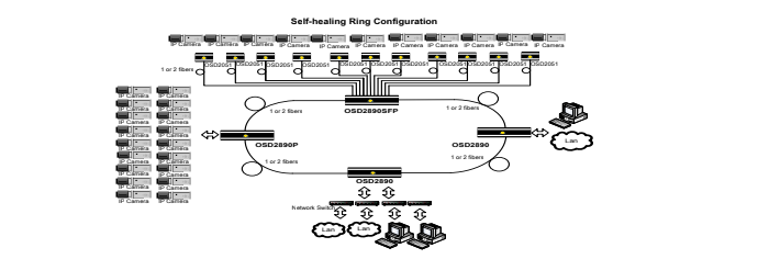
- Self-healing Gigabit Ethernet backbone networks
- Four 10G SFP+ trunk/uplink ports

specifications
ELECTRICAL
- Electrical Data Interface
- IEEE802.3i/802.3u/802.3ab, 10/100/1000Base-T Ethernet
- OSD2890P PoE
- IEEE802.3bt: Vin -1VDC @ 1.9Amp maximum (Ports 1-8 only)
- IEEE802.3at: Vin -1VDC @ 0.7Amp maximum
- IEEE802.3af: Vin -1VDC @ 0.35Amp maximum
- OSD2890P PoE Power Budget
- 720W maximum
- Configuration Connector
- Mini USB console port
- Alarms
- Four: two for Power Supply status
- Four: two user definable via the GUI as specified in the User Manual
- Alarm Interface
- Four opto-isolated relay drivers via two 4-way 3.5mm terminal blocks
- Control
- System reset
- Transmit Optical Power
- -15 to -7dBm into singlemode fiber
- -13 to -4dBm into multimode fiber
- -19 to -10dBm into multimode fiber (OSD2041LP only)
OPTICAL
- Optical Connector
- Dual LC on 2-fiber SFP modules or SC on 1-fiber SFP modules
- Trunk/Uplink Ports Optical Interface *
- IEEE802.3ae for 10GBASE-SR (MM: 300m), 10GBASE-LR (SM: 10km),
- 10GBASE_ER (SM: 40km), 10GBASE_ZR (SM: 80km), IEEE802.3z 1000Base-Lx/Sx
- Operating Mode
- >18dB: Half or full duplex for 10/100
- Full duplex for 1G and 10G
- Store-and-Forward
- Half-duplex back-pressure and IEEE802.3x full-duplex flow control
- See OSD SFP datasheet #10210000X and 10210G00X for full details on available optical SFP modules
INDICATORS
- OSD2890
- 1 x Power
- 24 x 10/100/1000Base-T: Link/ Activity
- 24 x 10/100/1000Base-T: Speed
- 4 x 10G: Link/ Activity/Speed
- OSD2890
- 1 x Power
- 24 x 10/100/1000Base-T: Link/ Activity
- 24 x 10/100/1000Base-T: Speed
- 4 x 10G: Link/ Activity/Speed
- 24 x 10/100/1000Base-T: PoE
PHYSICAL
- Operating Temperature Range
- -20°C to +70°C
- Relative Humidity
- 5 to 95% non-condensing
- OSD2890DC Power Requirements
- 10 – 36VDC @ 45VA Max via one 4-way 5.08mm terminal block
- OSD2890AC Power Requirements
- 90 – 264VAC @ 50VA Max via integrated IEC power inlet module
- OSD2890DAC Power Requirements
- 90 – 264VAC @ 55VA Max via two integrated IEC power inlet modules
- OSD2890P Power Requirements
- 47-57VDC @ 50VA Max (without PoE) and @770VA Max (with PoE) via one 8-way
- 5.08mm terminal block
- Dimensions of Module (mm)
- 440W x 300D x 44H
- Weight OSD2890
- 4.9kg
- Weight OSD2890P
- 5.8kg
Request a Quote
Learn More From
Frequently Asked Questions
Multimode fiber commonly comes in 50/125 μm or 62.5/125 μm core/cladding dimensions, with bandwidth capacities ranging from 200 MHz to 2 GHz, depending on the grade. Multimode systems typically support transmission distances of up to 5 km, making them suitable for short- to medium-range applications.
In contrast, singlemode fiber—usually 9–10/125 μm—offers significantly lower attenuation and effectively unlimited bandwidth, supporting links over 150 to 200 km, especially when paired with optical amplifiers and advanced transceivers.
While singlemode fiber is less expensive per meter, its associated transceivers and equipment tend to cost more than their multimode counterparts. That said, singlemode devices are generally compatible with both singlemode and multimode fiber, whereas multimode equipment works only with multimode fiber.
Let me know if you’d like this turned into a quick-reference table or visual comparison—it’d make a solid inclusion for a fiber deployment guide.
The link budget is the difference between the transmitter’s output power and the receiver’s sensitivity. This budget must account for all signal losses along the path, including:
- Fiber attenuation due to the transmission medium
- Connector losses, such as those at patch panels or equipment interfaces
- Splice losses from mechanical or fusion joints
- Link margin, which provides a buffer for unforeseen variations
The link margin typically ranges from 2–3 dB in tightly controlled environments to up to 10 dB in more variable conditions. It is designed to accommodate:
- Component aging (e.g., light sources may degrade and lose up to 3 dB over time)
- Temperature variations affecting transmitter output or receiver sensitivity (up to 3 dB may be needed for thermal fluctuations)
- Physical cable damage and repair-induced losses (usually minor, but more relevant in harsh or industrial settings)
Always design your system for worst-case scenarios to ensure reliability. However, don’t overlook the best-case condition either—some optical receivers may exhibit erratic behavior if the incoming signal is too strong.
First, verify the optical signal strength along the link. Use an optical power meter to measure the received power at the fiber’s end point. Typical transmit levels range from –8 dBm to –15 dBm, while the receiver sensitivity is around –31 dBm, giving you a link budget of approximately 16 dB. This margin supports transmission distances of up to 10 km on singlemode fiber and about 3–5 km on multimode fiber.
If the measured power falls below the receiver sensitivity, there’s a strong likelihood of issues with the installed fiber. Ideally, initial OTDR readings should have flagged such faults.
If not, inspect the patch cords currently in use for possible defects or misalignment. A frequent oversight is the use of mismatched patch cords.
Multimode fiber types are classified by the ISO/IEC 11801 standard into five main categories: OM1, OM2, OM3, OM4, and OM5. Each type differs in core size, bandwidth, supported data rates, and maximum transmission distances. Here’s a quick breakdown:

- OM3 and OM4 are laser-optimized and widely used in modern data centers.
- OM5 supports shortwave wavelength division multiplexing (SWDM), enabling multiple wavelengths over a single fiber for higher capacity.
- All OM types are backward compatible in terms of connectors, but mixing core sizes (e.g., OM1 with OM3) can cause performance issues.
