VIDEO MANAGEMENT SYSTEM

VIDEO MANGAMENT SYSTEM BROCHURE

PRODUCT DESCRIPTION

  • Honeywell’s MAXPRO VMS (Video Management System) effectively controls multiple video subsystems, optimizing video surveillance with efficiency and ease. MAXPRO VMS integrates seamlessly with your existing video infrastructure to collect, manage, and present video in a clear and concise manner, enhancing your overall surveillance capabilities.

MAXPRO® VMS

MAXPRO® VMS A Powerful Way to Manage Video Security

Honeywell’s MAXPRO VMS (Video Management System) effectively controls multiple video subsystems, optimizing video surveillance with efficiency and ease. MAXPRO VMS integrates seamlessly with your existing video infrastructure to collect, manage, and present video in a clear and concise manner, enhancing your overall surveillance capabilities.

Integration has never been so easy

AXPRO VMS revolutionizes video security by integrating seamlessly with our trusted Pro-Watch® security management system. This integration framework simplifies the development of plug-ins for video and security subsystems, ensuring comprehensive control over user provisioning, physical monitors, salvos, and video panels triggered by alarm and event actions from Pro-Watch. MAXPRO VMS also facilitates rapid interfacing with various video subsystems like NVRs, DVRs, and analog switchers, allowing for flexible application mixing within your current surveillance setup. It’s advanced technology that provides robust video security management capabilities.

Designed for Maximum Flexibility

The scalable architecture of MAXPRO® VMS allows for easy adjustments to your video surveillance network as required. Whether you need to scale down to a single client workstation and server configuration or expand to include multiple client workstations and servers, MAXPRO VMS supports these configurations seamlessly.

MAXPRO VMS operates on a client-server architecture, offering maximum flexibility, customization, and integration capabilities. The client component enables monitoring of sites and configuration of video devices such as cameras, monitors, and keyboards. On the server side, MAXPRO VMS includes the framework controller, database, and other essential core components to manage and store video data effectively.

Maximize Your Investment

MAXPRO VMS seamlessly integrates traditional analog components with modern digital and IP video systems into a unified surveillance network. Whether you’re managing network-based cameras and recorders or utilizing advanced video analytics, MAXPRO VMS’ top box architecture ensures compatibility and cohesive operation across diverse video subsystems.

  • Integrates seamlessly with Pro-Watch® for enhanced access control capabilities combined with comprehensive video functionalities.
  • Redundant server configuration increases system reliability, ensuring continuous operation even in case of server failures.
  • Operator messaging feature facilitates efficient data sharing of incidents among operators, promoting collaboration and swift response.
  • Supports auto-discovery of cameras connected to supported recorders, simplifying setup and maintenance tasks for surveillance networks.

MAXPRO® VMS Reaches New Heights in Your Market

MAXPRO VMS provides a versatile platform that can integrate seamlessly with diverse video devices across different industries worldwide. It offers a unified command and control interface to efficiently manage a wide range of products from Honeywell and other third-party vendors.

The platform intelligently assesses the capabilities of each subsystem across multiple sites, enabling unified management of analog and digital video devices. This includes analog switchers connected to analog monitors and cameras, as well as digital monitors, enterprise network video recorders (NVRs), and digital video recorders (DVRs). These subsystems can be managed using virtual switchers, multiplexers, and monitors to view and record images from modern IP cameras.

ARCHITECTURE

Open Architecture Gives You Scalability and Control

Easy Installation

  • Single Installation Software Package: Simplifies installation by consolidating all subsystems into one software package.
  • Auto-discovery of Supported Recorders: Automatically detects and integrates with supported recorders, enhancing setup efficiency.
  • Exceptional System Intelligence: Dynamically adapts to the capabilities of diverse subsystems, ensuring optimal performance across different video devices and configurations.

User-friendly Operation

  • User-Friendly Interface: Facilitates easy configuration and control of diverse devices from a centralized operator console.
  • My Devices List: Allows operators to group frequently used components such as cameras and recorders into personalized lists for quick access.
  • Web Client: Available for MAXPRO NVR recorders, offering a simple browser-based client without requiring additional software or licenses.
  • Advanced Alarm Management: Enables comprehensive alarm handling by providing access to video footage captured before, during, and after alarms. Operators can also view live video feeds from the cameras involved in the alarm event.

Fingertip Command and Control

  • Powerful Operator Messaging: Facilitates incident sharing among operators, enhancing collaboration and reducing investigation time. Operators can send salvo views of incidents to administrators or other operators with a simple drag-and-drop, ensuring quick and accurate incident review.
  • Advanced Timeline Control: Enables seamless navigation across multiple video recordings from various sources. Features like frame-by-frame analysis, bookmarking, looping, and digitally-signed clip export provide precise control over monitoring activities.
  • Surrounding Cameras Mode: Simplifies tracking subjects of interest by offering presets that quickly bring the nearest camera into view, ensuring efficient surveillance management.
  • Monitor Control: Allows comprehensive control over analog and digital monitors from a single workstation or joystick keyboard, transforming the system into a unified analog and digital matrix for enhanced operational flexibility.

Expanded Functionality

  • Powerful Operator Messaging: Facilitates incident sharing among operators, enhancing collaboration and reducing investigation time. Operators can send salvo views of incidents to administrators or other operators with a simple drag-and-drop, ensuring quick and accurate incident review.
  • Advanced Timeline Control: Enables seamless navigation across multiple video recordings from various sources. Features like frame-by-frame analysis, bookmarking, looping, and digitally-signed clip export provide precise control over monitoring activities.
  • Surrounding Cameras Mode: Simplifies tracking subjects of interest by offering presets that quickly bring the nearest camera into view, ensuring efficient surveillance management.
  • Monitor Control: Allows comprehensive control over analog and digital monitors from a single workstation or joystick keyboard, transforming the system into a unified analog and digital matrix for enhanced operational flexibility.

Seamless Integration

  • Integration with Enterprise Access Control and Alarm Intrusion Systems: MAXPRO VMS seamlessly integrates with enterprise-wide access control and alarm intrusion systems, enhancing overall security management capabilities.
  • Integration with Pro-Watch®: Provides superior access control capabilities integrated with advanced video functionalities, ensuring comprehensive security management.
  • Scalable Architecture: Supports integration with Honeywell’s and third-party DVRs and NVRs, offering a scalable architecture capable of accommodating multiple cameras and camera servers, thereby meeting diverse surveillance needs effectively.

Request a Quote

Ready to Work Together? Build a project with us!

Learn More From

Frequently Asked Questions

Multimode fiber commonly comes in 50/125 μm or 62.5/125 μm core/cladding dimensions, with bandwidth capacities ranging from 200 MHz to 2 GHz, depending on the grade. Multimode systems typically support transmission distances of up to 5 km, making them suitable for short- to medium-range applications.

In contrast, singlemode fiber—usually 9–10/125 μm—offers significantly lower attenuation and effectively unlimited bandwidth, supporting links over 150 to 200 km, especially when paired with optical amplifiers and advanced transceivers.

While singlemode fiber is less expensive per meter, its associated transceivers and equipment tend to cost more than their multimode counterparts. That said, singlemode devices are generally compatible with both singlemode and multimode fiber, whereas multimode equipment works only with multimode fiber.

Let me know if you’d like this turned into a quick-reference table or visual comparison—it’d make a solid inclusion for a fiber deployment guide.

The link budget is the difference between the transmitter’s output power and the receiver’s sensitivity. This budget must account for all signal losses along the path, including:

  • Fiber attenuation due to the transmission medium
  • Connector losses, such as those at patch panels or equipment interfaces
  • Splice losses from mechanical or fusion joints
  • Link margin, which provides a buffer for unforeseen variations

The link margin typically ranges from 2–3 dB in tightly controlled environments to up to 10 dB in more variable conditions. It is designed to accommodate:

  • Component aging (e.g., light sources may degrade and lose up to 3 dB over time)
  • Temperature variations affecting transmitter output or receiver sensitivity (up to 3 dB may be needed for thermal fluctuations)
  • Physical cable damage and repair-induced losses (usually minor, but more relevant in harsh or industrial settings)

Always design your system for worst-case scenarios to ensure reliability. However, don’t overlook the best-case condition either—some optical receivers may exhibit erratic behavior if the incoming signal is too strong.

First, verify the optical signal strength along the link. Use an optical power meter to measure the received power at the fiber’s end point. Typical transmit levels range from –8 dBm to –15 dBm, while the receiver sensitivity is around –31 dBm, giving you a link budget of approximately 16 dB. This margin supports transmission distances of up to 10 km on singlemode fiber and about 3–5 km on multimode fiber.

If the measured power falls below the receiver sensitivity, there’s a strong likelihood of issues with the installed fiber. Ideally, initial OTDR readings should have flagged such faults.

If not, inspect the patch cords currently in use for possible defects or misalignment. A frequent oversight is the use of mismatched patch cords.

Multimode fiber types are classified by the ISO/IEC 11801 standard into five main categories: OM1, OM2, OM3, OM4, and OM5. Each type differs in core size, bandwidth, supported data rates, and maximum transmission distances. Here’s a quick breakdown:

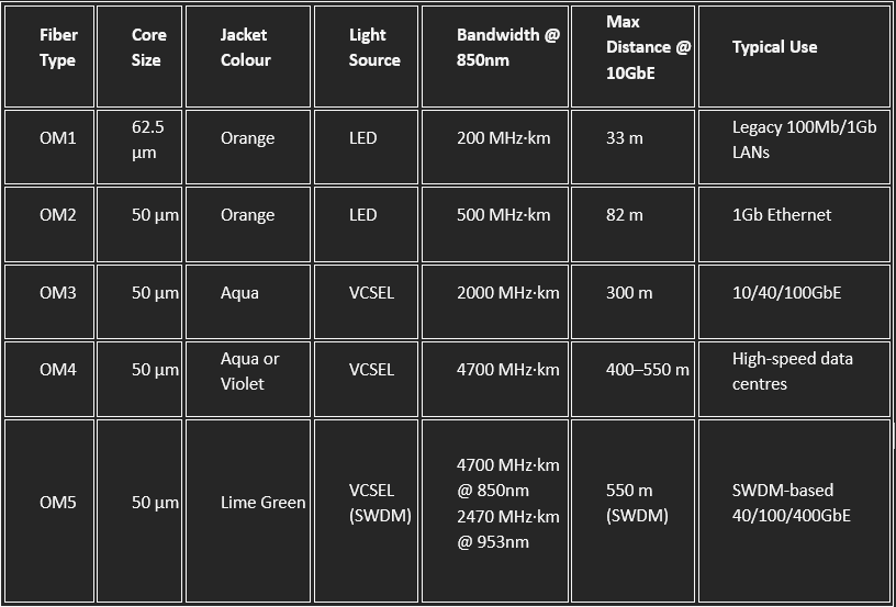
  • OM3 and OM4 are laser-optimized and widely used in modern data centers.
  • OM5 supports shortwave wavelength division multiplexing (SWDM), enabling multiple wavelengths over a single fiber for higher capacity.
  • All OM types are backward compatible in terms of connectors, but mixing core sizes (e.g., OM1 with OM3) can cause performance issues.